Showing posts with label Networking. Show all posts

Wednesday, November 23, 2016

Configure Static IP On CentOS 6


Below steps will show configuration to set static IP address in Cent-OS machine.

    Network configuration files are under "/etc/sysconfig/network-scripts".
    We can open the file with editor like nano, vi, vim etc...
   
    Here I will use vi editor.
   
    In this server we will set Static IP for eth0 Ethernet port

1 - Start your server running Cent-OS enter root user credentials and login.

2 - Type the command,

         vi /etc/sysconfig/network-scripts/ifcfg-eth0

    This will open network configuration file, edit below lines:

         NM_CONTROLLED=yes
         ONBOOT=yes
         TYPE=Ethernet
         BOOTPROTO=static
         IPADDR=192.168.1.44            # Replace IP with your new
         NETMASK=255.255.255.0     # Replace IP with your subnet mask

3 - Type the command,

         vi /etc/sysconfig/network
   
    This will open file to set default gateway, edit below lines:

         NETWORKING=yes
         GATEWAY=192.168.1.1        # Replace IP with your gateway IP

4 - Type the command,

          vi /etc/resolv.conf
   
    This will open file to set DNS,

          nameserver 8.8.8.8                # Replace IP with your DNS IP
          nameserver 192.168.1.1        # Replace IP with your DNS IP

5 - To apply changes restart network interface, Type the command.
   
          /etc/init.d/network restart
   
NOTE:
Some time you might face issue in accessing your system. It can be due to firewall.
       
        To stop firewall temporary execute command,

            service iptables stop
           
        To stop firewall permanently execute command,

            service iptables stop
            chkconfig iptables off


ENJOY! and Stay connected.

Wednesday, June 8, 2016

Networking between Host Computer and VM In VirtualBox

Hi friends,

How to access Virtual machine in Oracle VM VirtualBox from host computer to?


If you have a VM installed in virtual box, of your host system and want to access it from your host system. If your system is connected to a switch you can set network attached option as bridge and can access it in your network as a remote system.

But if you have a single system and want to access VM installed in virtual box of your host system without a switch.

Here I will show you how to do it, use VirtualBox host only Ethernet network adapter for communicating between VM and your Host computer. Host-only networking is another networking option in virtual box network.

With bridged networking option, the virtual machines can communicate with internet through physical Ethernet.

But as the name indicating there is only Host for networking. This adapter will connect VM in Virtual box and Host system. No outside connection (Internet or Other network).

Host only network adapter is for internal networking between VM and your Host computer only.

Lets check how to do so.

1- Open Network and Sharing center > Adapter Settings on your host computer and look for VirtualBox Host-Only Network adapter.

2- Double click on Internet Protocol Version 4. Put a Static IP. DNS and gateway are optional.

3- Now start Virtual Box application, go to  Settings > Network. Select Host-Only Adapter from Attached to drop down menu, and click OK.

4- Now start VM in Virtual Box and go to Network Adapter settings, Right click and select Properties.


5- Double click on Internet Protocol Version 4. Assign a Static IP address of the same range that you assigned to the your host system. DNS and gateway are optional.


6- Open command prompt then try to ping host and vice versa. Refer the screen shots below.


My Host (Windows 7) Static IP :- 10.10.44.100
Virtual Box VM (Windows 10) Static IP :-
10.10.44.254


Virtual box Windows 10 is able to ping Host Windows 7 and vice versa

ENJOY! and Stay connected.

Tuesday, April 14, 2015

How to use a Ethernet splitter.


Imagine u have One Ethernet point came in your room and you want to connect two device one your laptop and other one is your desktop.

Now what will you do?


You can purchase a switch or a hub and connect your devices with it, Or You May pull a new wire for the your second device.
But both the options are expensive.

I have one more options for you which is cheap and easy as compared to other.
You can use a Ethernet splitter.


But how does it work?
You might know a Ethernet cable has 8 wires.
But among them only 4 cables are only used to transmit and receive data for a device. So we can use the other 4 cables to transmit and receive data but for other device.


For more check the video below.
ENJOY! and Stay connected.

Tuesday, February 17, 2015

List of network protocols on OSI model.

In this post we will know about network protocols organized by OSI model.

This is list of network protocols, classified by Open Systems Interconnection (OSI) model layers.


OSI model

Layer 1 (Physical Layer) 
>> Telephone network modems- V.92
>> IRDA physical layer
>> USB physical layer
>> EIA RS-232, EIA-422, EIA-423, RS-449, RS-485
>> Ethernet physical layer Including 10BASE-T, 10BASE2, 10BASE5, 100BASE-TX, 100BASE-FX, 100BASE-T, 1000BASE-T, 1000BASE-SX and other varieties
>> Varieties of 802.11 Wi-Fi physical layers
>> DSL
>> ISDN
>> T1 and other T-carrier links, and E1 and other E-carrier links
>> SONET/SDH
>> Optical Transport Network (OTN)
>> GSM Um air interface physical layer
>> Bluetooth physical layer
>> ITU Recommendations: see ITU-T
>> IEEE 1394 interface
>> TransferJet physical layer
>> Etherloop
>> ARINC 818 Avionics Digital Video Bus
>> G.hn/G.9960 physical layer
>> CAN bus (controller area network) physical layer
>> Mobile Industry Processor Interface physical layer

Layer 2 (Data Link Layer)
>> ARCnet Attached Resource Computer NETwork
>> CDP Cisco Discovery Protocol
>> DCAP Data Link Switching Client Access Protocol
>> Distributed Multi-Link Trunking
>> Distributed Split Multi-Link Trunking
>> Dynamic Trunking Protocol
>> Econet
>> Ethernet
>> FDDI Fiber Distributed Data Interface
>> Frame Relay
>> ITU-T G.hn Data Link Layer
>> HDLC High-Level Data Link Control
>> IEEE 802.11 WiFi
>> IEEE 802.16 WiMAX
>> LACP Link Aggregation Control Protocol
>> LattisNet
>> LocalTalk
>> L2F Layer 2 Forwarding Protocol
>> L2TP Layer 2 Tunneling Protocol
>> LAPD Link Access Procedures on the D channel
>> LLDP Link Layer Discovery Protocol
>> LLDP-MED Link Layer Discovery Protocol - Media Endpoint Discovery
>> PAgP - Cisco Systems proprietary link aggregation protocol
>> PPP Point-to-Point Protocol
>> PPTP Point-to-Point Tunneling Protocol
>> Q.710 Simplified Message Transfer Part
>> Multi-link trunking Protocol
>> RPR IEEE 802.17 Resilient Packet Ring
>> SLIP Serial Line Internet Protocol (obsolete)
>> StarLAN
>> STP Spanning Tree Protocol
>> Split multi-link trunking Protocol
>> Token ring a protocol developed by IBM; the name can also be used to describe the token passing ring logical topology that it popularized.
>> VTP VLAN Trunking Protocol
>> VLAN Virtual Local Area Network

Layer 3 (Network Layer)
>> CLNP Connectionless Networking Protocol
>> EGP Exterior Gateway Protocol
>> EIGRP Enhanced Interior Gateway Routing Protocol
>> IGMP Internet Group Management Protocol
>> IGRP Interior Gateway Routing Protocol
>> IPv4 Internet Protocol version 4
>> IPv6 Internet Protocol version 6
>> IPSec Internet Protocol Security
>> IPX Internetwork Packet Exchange
>> Routed-SMLT
>> SCCP Signalling Connection Control Part
>> AppleTalk DbP
>> ESP Encapsulating Security Payload over IP or IPSec
>> GRE Generic Routing Encapsulation for tunneling
>> BGP Border Gateway Protocol
>> OSPF Open Shortest Path First

Layer 4 (Transport Layer)
>> AH Authentication Header over IP or IPSec
>> IL Originally developed as transport layer for 9P
>> SCTP Stream Control Transmission Protocol
>> Sinec H1 for telecontrol
>> SPX Sequenced Packet Exchange
>> TCP Transmission Control Protocol
>> UDP User Datagram Protocol
>> DCCP Datagram Congestion Control Protocol
>> RTP

Layer 5 (Session Layer)
>> 9P Distributed file system protocol developed originally as part of Plan 9
>> NetBIOS, File Sharing and Name Resolution protocol - the basis of file sharing with Windows.
>> NetBEUI, NetBIOS Enhanced User Interface
>> NCP NetWare Core Protocol
>> NFS Network File System
>> SMB Server Message Block
>> SOCKS "SOCKetS"

Layer 6 (Presentation Layer)
>> TLS Transport Layer Security,
>> JPEG
>> MP3
>> MPEG

Layer 7 (Application Layer)
>> ADC, A peer-to-peer file sharing protocol
>> AFP, Apple Filing Protocol
>> BACnet, Building Automation and Control Network protocol
>> BitTorrent, A peer-to-peer file sharing protocol
>> BGP Border Gateway Protocol
>> BOOTP, Bootstrap Protoc;
>> CAMEL, an SS7 protocol tool for the home operator
>> Diameter, an authentication, authorization and accounting protocol
>> DICOM includes a network protocol definition
>> DICT, Dictionary protocol
>> DNS, Domain Name System
>> DSM-CC Digital Storage Media Command and Control
>> DSNP, Distributed Social Networking Protocol
>> DHCP, Dynamic Host Configuration Protocol
>> ED2K, A peer-to-peer file sharing protocol
>> Finger, which gives user profile information
>> Gnutella, a peer-to-peer file-swapping protocol
>> Gopher, a hierarchical hyperlinkable protocol
>> HTTP, Hypertext Transfer Protocol
>> HTTPS, Hypertext Transfer Protocol Secure
>> IMAP, Internet Message Access Protocol
>> IRC, Internet Relay Chat
>> ISUP, ISDN User Part
>> LDAP Lightweight Directory Access Protocol
>> MIME, Multipurpose Internet Mail Extensions
>> MSNP, Microsoft Notification Protocol (used by Windows Live Messenger)
>> MAP, Mobile Application Part
>> Mosh, Mobile Shell
>> NNTP, Network News Transfer Protocol
>> NTP, Network Time Protocol
>> NTCIP, National Transportation Communications for Intelligent

>> Transportation System Protocol
>> POP3 Post Office Protocol Version 3
>> RADIUS, an authentication, authorization and accounting protocol
>> RDP, Remote Desktop Protocol
>> Rlogin, a UNIX remote login protocol
>> rsync, a file transfer protocol for backups, copying and mirroring
>> RTP, Real-time Transport Protocol
>> RTSP, Real-time Transport Streaming Protocol
>> SSH, Secure Shell
>> SISNAPI, Siebel Internet Session Network API
>> SIP, Session Initiation Protocol, a signaling protocol
>> SMTP, Simple Mail Transfer Protocol
>> SNMP, Simple Network Management Protocol
>> SOAP, Simple Object Access Protocol
>> SMB, Microsoft Server Message Block Protocol
>> STUN, Session Traversal Utilities for NAT
>> TUP, Telephone User Part
>> Telnet, a remote terminal access protocol
>> TCAP, Transaction Capabilities Application Part
>> TFTP, Trivial File Transfer Protocol, a simple file transfer protocol
>> WebDAV, Web Distributed Authoring and Versioning
>> Extensible Messaging and Presence Protocol (XMPP)


For more detail click here....
Source: Wikipedia

ENJOY! and stay connected.

Monday, February 16, 2015

OSI Model (7 Layers of OSI Model, and How it works).

The most basic thing to understand network is to understand about OSI model. It is one of the most important tools which help us to know how networking devices like router, switch, hub, computer, etc... works.

To understand OSI model easily, let’s take a real life example. Many of us have posted a Greeting card or any Letter to anyone.
 

Generally to do it, we have to follow at least below steps:-
1 - Write your letter or Purchase a Greeting card.
2 - Pack it into an envelope.
3 - Write sender and receiver address on that envelope
4 - Stamp it.
5 - Go to the post box and drop it into it.

The above example, signify that we have to go through some steps in a specific order to send any message with each other. The networking too use a set of steps to send and receive any data which is called OSI model. The ISO model has 7 steps. Each step is called as a Layer. Each layer is arranged from top to bottom (numbering from 7 to 1). When a device send information to another the data goes from top to bottom layer (7 to 1). But if a device receives any data it will go from bottom to top (1 to 7). When data goes from top to bottom layer, a header is added to it at every layer. This is called encapsulation.

Lets Understand each layer how they work.


# Layer 7 – Application layer
 This is the closest layer to the user. It provides the interface between the applications we use and the next layers. But don't thing programs you are using (like a web browser – IE, Firefox, Opera, etc) are not a part of Application layer. Telnet, FTP, SMTP, HTTP, HTTPs, POP3 are examples of Application layer.

# Layer 6 – Presentation layer
Presentation layer ensures that the data passing is in a appropriate form for receiving device. It can be also called as translator of the network. For example, if we want to send an song the Presentation layer will format our data into MP3 format. Or we want to send photos to any of our friend, the Presentation layer will format our data into GIF, JPG, PNG etc... format.

# Layer 5 – Session layer
The Session Layer establishes, maintains and ends communication with the receiving device.

# Layer 4 – Transport layer
This layer maintains data flow and provides for error checking and recovery between the devices. The best example of Transport layer is Transmission Control Protocol (TCP) and User Datagram Protocol (UDP).

# Layer 3 – Network layer
This layer provides logical addresses which routers will use to determine the path to the destination (the last destination). In most cases, the logic addresses here means the IP addresses (including source & destination IP addresses).
 

# Layer 2 – Data Link Layer
The Data Link layer formats the message into a data frame, and adds a header containing the hardware destination and source address to it. This header is responsible for finding the next destination device on a local network.

NOTE:- Network layer (layer 3) is responsible for finding the path to the last destination (network) but it doesn’t care about who will be the next receiver. It is the Layer 2 that helps data to reach the next destination.

Network layer is divide into 2 sub-layers:
>> Logical link control (LLC)
>> Media access control (MAC).


The LLC functions include:
+ Managing frames to upper and lower layers
+ Error Control
+ Flow control

The MAC sublayer carries the physical address of each device on the network. This address is more commonly called a device’s MAC address. MAC address is a 48 bits address which is burned into the NIC card on the device by its manufacturer.


# Layer 1 – Physical layer

The Physical Layer defines the physical characteristics of the network such as connections, voltage levels and timing.


I summarize all the important functions of each layer in the table:-

Layer
Description
Popular Protocols
Protocol Data Unit
Devices operate in this layer
Application
# User interface
HTTP, FTP, TFTP, Telnet, SNMP, DNS…
Data

Presentation
# Data representation, encryption & decryption
# Video (WMV, AVI…)
Data

# Bitmap (JPG, BMP, PNG…)
# Audio (WAV, MP3, WMA…)

Session
# Setup, monitor & terminate the connection session
# SQL, RPC, NETBIOS names…
Data

Transport
# Flow control (Buffering, Windowing, Congestion Avoidance) helps prevent the loss of segments on the network and the need for retransmission
# TCP (Connection-Oriented, reliable)
Segment

# UDP (Connectionless, unreliable)
Network
# Path determination
# IP
Packet/Datagram
Router
# Source & Destination logical addresses
# IPX

# AppleTalk
Data Link
# Physical addresses
# LAN
Frame
Switch, Bridge
# WAN (HDLC, PPP, Frame Relay…)
Includes 2 layers:

# Upper layer: Logical Link Control (LLC)

# Lower layer: Media Access Control (MAC)

Physical
Encodes and transmits data bits
# FDDI, Ethernet
Bit (0, 1)
Hub, Repeater…
# Electric signals
# Radio signals

Thursday, February 12, 2015

Bypass Hardware or software Firewall/Proxy to access block sites [100% safe and working].

Hello friends generally in many of the offices, schools and even in few countries, it’s very common that to social media and many other sites like Facebook, Twitter, YouTube, Gaming sites etc... are blocked. Most of the times, it is done to increase productivity and protect users interact with unofficial content while work. We’re are having many different ways by which we can bypass school or office Firewall/Proxy.


In this post, We’ll see how to bypass school or office firewall/Proxy using Tor Browser (It's safe and secure as compared to any other).

What Is Tor?

The name "Tor" refer to several different components.
The Tor browser is a freeware program which we can run on your computer. It helps us to be hidden and use safe Internet. The most interesting and good thing about Tor
browser is that it doesn't require any kind of installation. Due to which auditor will not find any trace in register, add remove programs etc..., everything is kept in the location where Tor browser is extracted. Tor protects us by bouncing our communications around a distributed network of relays run by volunteers all around the world. It prevents somebody watching our Internet connection from learning what sites we visit, and it prevents the sites we visit from learning our physical location. This set of volunteer relays is called the Tor network. We can read more about, How Tor works from below Link.

How to use Tor Browser to bypass firewall/proxy to access block sites?
1 - Download Tor Browser from HERE. (DOWNLOAD)
2 - Execute the Downloaded .exe file. It will extract the content on your desktop, in a folder named 'Tor Browser' (by default).
3 - Open the 'Tor Browser' folder and execute 'Start Tor Browser' shortcut present there.

If not having any proxy settings.
4 - Click on Next > Next > Connect.
5 - Tor browser will be started and you may now access all blocked sites.

If using proxy settings.
4 - Click on 'Configure' button.
5 - Select 'Yes' under 'Does this computer need to use a proxy to access the internet?' and click on 'Next'.
6 - Click on 'Connect'.
5 - Tor browser will be started and you may now access all blocked sites.

To use Tor browser on other Operating system Linux, Mac, Android etc... visit below link.


Enjoy! and stay connected.

Friday, February 6, 2015

Internet vs Intranet vs Extranet

Internet
Internet is the world-wide network of devices accessible to anyone, or we can also say is is a network of Computers which is open for all. It itself contains a large number of intranets. It has unlimited number of users, and has a unlimited visitors traffic too. It is never ending source of information. Collection of various LANs, WANs, MANs. etc... creates a internet.


Intranet
Intranet is network of device for a specific group of users. It can not be accessed from Internet. It has a limited number of Users. It contains only information required for the group of users. It is generally any LAN, MAN or WAN.


Extranet
An Extranet is actually an Intranet that is accessible to authorized outsiders with few limitation. The actual server is behind a firewall. The firewall helps to control access between the Intranet and Internet. It allow to access the Intranet only to some people. The access level can be controlled and can be set to different levels for individuals or groups of outside users. The access can be based on a username and password,  IP address or physical address (MAC ID).


Thursday, January 29, 2015

Daisy Chain Topology

In a daisy chain, one network node is attached to the next in a line or chain. A daisy chain topology can be linear, where the first and last two nodes are not connected, or a ring, where the first and last nodes are connected. A ring topology allows for bidirectional passing, whereas in a linear setup, a message must go from one machine to another in one direction.


For Other Topologies Click HERE

Hybrid Topology

Hybrid networks use a combination of any two or more topologies, in such a way that the resulting network does not exhibit one of the standard topologies (e.g., bus, star, ring, etc.). For example a tree network connected to a tree network is still a tree network topology. A hybrid topology is always produced when two different basic network topologies are connected. Two common examples for Hybrid network are: star ring network and star bus network

A Star ring network consists of two or more star topologies connected using a multi station access unit (MAU) as a centralized hub.
A Star Bus network consists of two or more star topologies connected using a bus trunk (the bus trunk serves as the network's backbone).


For Other Topologies Click HERE

Tree Topology

A tree topology is combination of bus topology and star topology. The nodes of bus topology are replaced with standalone star topology networks. This results in both disadvantages of bus topology and advantages of star topology.

Advantages
It is scalable. Secondary nodes allow more devices to be connected to a central node.
Point to point connection of devices.
Having different levels of the network makes it more manageable hence easier fault identification and isolation.

Disadvantages
Maintenance of the network may be an issue when the network spans a great area.
Since it is a variation of bus topology, if the backbone fails, the entire network is crippled.

Example of this network could be cable TV technology. Other examples are in dynamic tree based wireless networks for military, mining and otherwise mobile applications


For Other Topologies Click HERE

Mesh Topology

The value of fully meshed networks is proportional to the exponent of the number of subscribers, assuming that communicating groups of any two endpoints, up to and including all the endpoints, is approximated by Reed's Law.

Type of Mesh :-

Fully connected network
Partially connected


For Other Topologies Click HERE

Ring Topology

In a ring topology, every device has exactly two neighbors for communication purposes. All messages travel through a ring in the same direction (either "clockwise" or "anticlockwise"). A failure in any cable or device breaks the loop and can take down the entire network.
To implement a ring network, one typically uses FDDI, SONET, or Token Ring technology. Ring topologies are found in some office buildings or school campuses.


For Other Topologies Click HERE

Star Topology


In local area networks with a star topology, each network host is connected to a central hub with a point-to-point connection. In Star topology every node (computer workstation or any other peripheral) is connected to a central node called hub or switch. The switch is the server and the peripherals are the clients. The network does not necessarily have to resemble a star to be classified as a star network, but all of the nodes on the network must be connected to one central device. All traffic that traverses the network passes through the central hub. The hub acts as a signal repeater. The star topology is considered the easiest topology to design and implement. An advantage of the star topology is the simplicity of adding additional nodes. The primary disadvantage of the star topology is that the hub represents a single point of failure.

Tuesday, January 27, 2015

Bus Topology

In bus topology all device share single communication line or cable. All devices are connected to this shared line. Bus topology may have problem while more than one hosts sending data at the same time. Therefore, generally the bus topology either uses CSMA technology or set one host has Bus Master to solve the issue.
In this failure of a device does not affect the others. But if the shared line gets failed communication between all other devices fail.

Both ends of the shared line has a terminator. The data can be sent in only one direction at a time and as soon as it reaches the extreme end, the terminator removes the data from the line.   

To set up Bus Topology required a set of cables, few connectors and most importantly the terminators.

Cables :- Generally while configuring bus topology, two different grades of cables are used. One thick (as a trunk or backbone/main cable) and other thin (as branch cables that used to connect the devices with the backbone cable).

T-Connectors:- T-Connecters were used to join the branch cables with the trunk and were T in shapes.

Terminators:- Terminators are connected to each end of the trunk. They ground and neutralize all garbage data of the trunk cable that was generated because of the collisions that used to occur in a bus topology.

British Naval Connectors or BNCs:- These connectors are used to connect the branch cables with the PCs. The branch cables were crimped with the BNC connectors and then the connectors were connected to the available ports in the NICs (LAN cards) that were installed in the PCs.


For Other Topologies Click HERE

Network topology

Computer network topology is the way various components of a network (like nodes, links, peripherals, etc) are arranged. Network topologies define the layout, virtual shape or structure of network, not only physically but also logically. The way in which different systems and nodes are connected and communicate with each other is determined by topology of the network. Topology can be physical or logical. Physical Topology is the physical layout of nodes, workstations and cables in the network; while logical topology is the way information flows between different components.

There are two basic categories of network topologies:-
* Physical Topologies
* Logical Topologies

Physical Topologies
The cabling layout used to link devices is the physical topology of the network. This refers to the layout of cabling, the locations of nodes, and the interconnections between the nodes and the cabling.

Logical Topologies
The logical topology is the way that the signals transmits in the network media, or the way that the data passes through the network from one device to the next without regard to the physical interconnection of the devices. A network's logical topology is not necessarily the same as its physical topology.

Types of Network Topologies :-
1. Point-to-point
2. Bus
3. Star
4. Ring
5. Mesh
6. Tree
7. Hybrid
8. Daisy chain


Saturday, January 24, 2015

Tuesday, January 20, 2015

Type of Computer Network.


Based on geographical area there are many types of networks.
Some of the important types Of Computer networks are :-

Personal Area Networks (PAN) :
A network contained within a user's home to connects his/her digital devices.

The range of PAN is 1M to 50M 
Example :- connection between to cellphone through WiFi or Bluetooth.
 

Local Area Networks (LAN) :
A LAN is a network that connects computers and devices in a limited geographical area such as a home, school, office building, or closely positioned group of buildings.The range of LAN is 50 to 100M

Example :-  A small office, class room, cyber cafe.
 

Metropolitan Area Networks (MAN) :
A metropolitan area network (MAN) is computer network larger than a local area network, covering an area of a few city blocks to the area of an entire city, possibly also including the surrounding areas. The network can extend up to 20 miles (30 km) long and operate at speeds of 34–155 Mbit/s.


Wide Area Networks (WAN) :
A WAN is a computer network that covers a large geographic area such as a city, country, or spans even intercontinental distances. A WAN uses a communications channel that combines many types of media such as telephone lines, cables, and air waves. A WAN often makes use of transmission facilities provided by common carriers, such as telephone companies.


Home Area Network (HAN) :
A HAN is a residential LAN used for communication between digital devices typically deployed in the home, usually a small number of personal computers and accessories, such as printers and mobile computing devices. An important function is the sharing of Internet access, often a broadband service through a cable TV or digital subscriber line (DSL) provider.


Storage Area Network (SAN) :
A SAN is a dedicated network that provides access to consolidated, block level data storage. SANs are primarily used to make storage devices, such as disk arrays, tape libraries, and optical jukeboxes, accessible to servers so that the devices appear like locally attached devices to the operating system. A SAN typically has its own network of storage devices that are generally not accessible through the local area network by other devices. The cost and complexity of SANs dropped in the early 2000s to levels allowing wider adoption across both enterprise and small to medium sized business environments.


Campus Area Network (CAN) :
A campus area network (CAN) is made up of an interconnection of LANs within a limited geographical area. The networking equipment (switches, routers) and transmission media (optical fiber, copper plant, Cat5 cabling, etc.) are almost entirely owned by the campus tenant / owner (an enterprise, university, government, etc.). The range of CAN is 1KM to 5KM
Example:- a university campus network is likely to link a variety of campus buildings to connect academic colleges or departments, the library, and student residence halls.


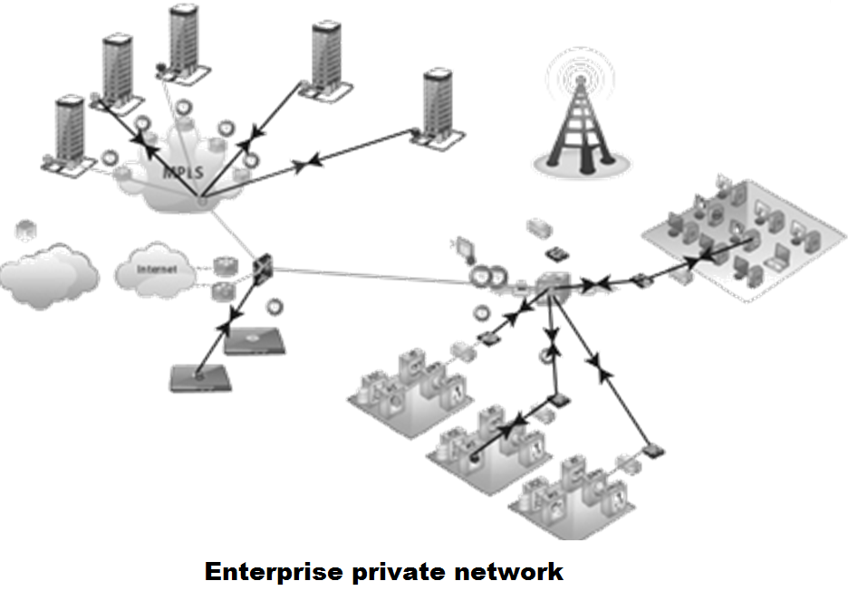
Enterprise Private Network :
An enterprise private network is a network that a single organization builds to interconnect its office locations so they can share computer resources.
Example:- Production sites, head offices, remote offices, shops.


Virtual Private Network (VPN) :
VPN is a network that is constructed by using public wires — usually the Internet — to connect to a private network, such as a company's internal network. There are a number of systems that enable you to create networks using the Internet as the medium for transporting data.